Any Embedded learning path starts with Blinky project Just like we start our Language journey with a simple Hello World project. For generating such blinky project you need following simple ingredients to work with:
- MCU
- LED
- programmer
- general purpose components etc.
So for this tutorial we are going to use out trusty STM32 blue pill board with a ST Link programmer. All above components are already available on given board except for programmer which we are using separately.
The Blinky project simply involves toggling an LED ON and OFF at a fixed interval.
While it sounds basic, it teaches key embedded concepts:
- GPIO configuration
- Digital output control
- Clock configuration
- Delay generation (software or timer-based)
- Understanding MCU register/peripheral interaction
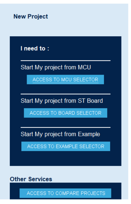
So lets start from creating a project in STM32CubeMX. Open File -> New Project or Ctrl + N or you can select option “ACCESS TO MCU SELECTOR” from following list directly
NOTE: At multiple location you might encounter a downloading screen don’t worry these screens are not showing any malware / virus activities. These are basically STM32 software’s updating there database with daily updates & patches for new info’s or bug fixes. So don’t worry & let process get completed. Usually for first time this process may take several minutes so please keep patience. Once process is completed, you will be greeted with following selection window.
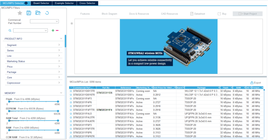
Here select MCU/MPU selector screen Will understand other screens in future updates. Now enter part no STM32F103C8T6 in front of Commercial Part Number to select MCU for our Blue Pill Board Now here in case if you are using any other board make sure correct MCU part no. For MCU part no please refer datasheet or user manual or schematics of the given board.
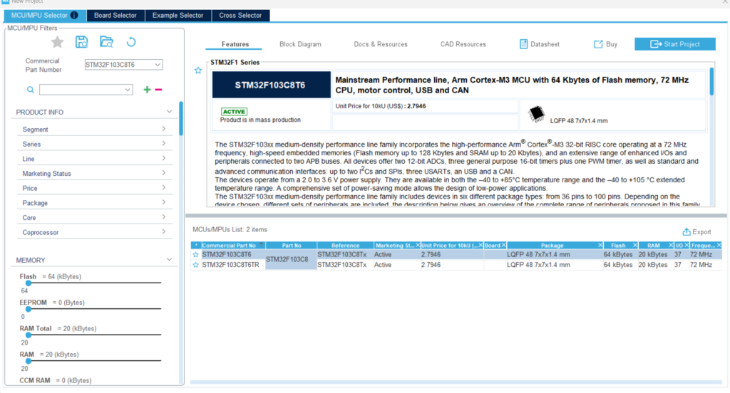
After selecting the MCU part you can select the part from given list About the Selected MCU a brief data can be found in the above part of the selection Here you can get different info about MCU such as block diagram, its features, resources, CAD info such as footprints etc. You can access this info as per your need. After selecting a MCU Click on Start Project to start the process
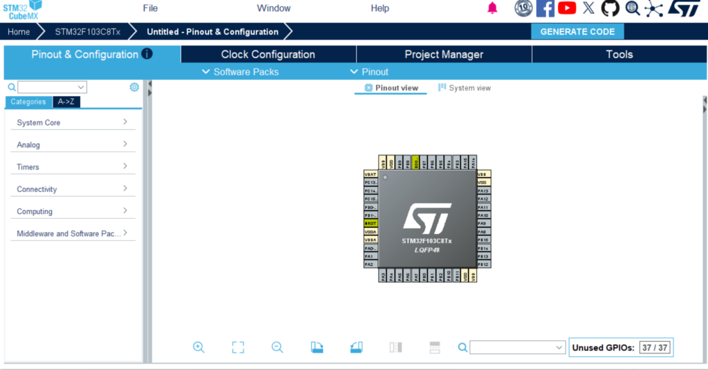
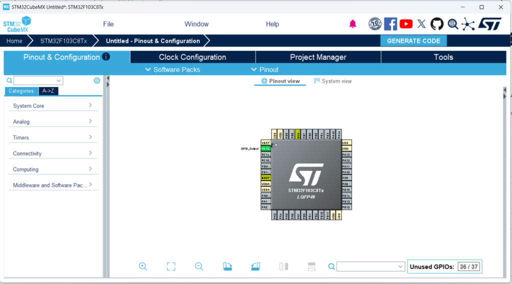
You will be greeted with MCU pin selector with its features & options.
Now any MCU you use make sure you have 5 following things taken care.
- Crystal Clock
- Power Supply
- Special pins
- Reset pin
- Programmer
Lets talk about them one by one
1. Crystal Clock
A microcontroller needs a clock source to execute instructions. Think of the clock as the heartbeat of the MCU. Without it, the processor cannot perform any operations.
Depending on the microcontroller, the clock source can be:
- Internal RC Oscillator
- External Crystal Oscillator
- Ceramic Resonator
- External Clock Generator
For simple projects, the internal oscillator is often sufficient. However, applications requiring precise timing, communication protocols, or high-speed operation usually rely on an external crystal. For our operation we are going to choose the basic given settings
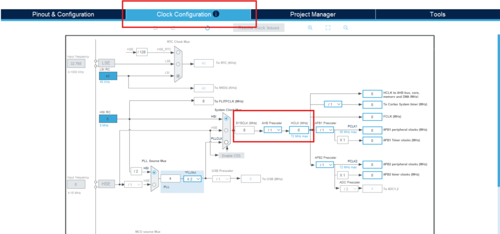
As you can see in image we had kept crystal at 8MHz which is pretty low compare to what this MCU can reach(72MHz Max) But for most DIY operations this frequency is more than enough.
2. Power Supply
No electronic device can function properly without a stable power supply, and microcontrollers are no exception. As we are using a development board we just need to supply specified supply. For Blue Pill board we can use STLink inbuilt supply or a Micro-USB cable would be enough.
Before powering an MCU, verify:
- Operating voltage range (3.3V, 5V, etc.)
- Maximum current requirements
- Power-up sequencing requirements
- Noise filtering requirements
If you are planning to design your own board. Then a Good practices include:
- Keep power traces short and low impedance.
- Place decoupling capacitors close to every power pin.
- Use a stable voltage regulator.
- Separate analog and digital supplies when required.
NOTE: Even the best-written firmware cannot compensate for a noisy or unstable power supply.
3. Special Pins
Most microcontrollers include certain pins that serve critical functions beyond normal GPIO operation.
Examples include:
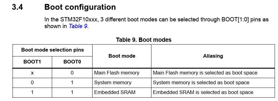
- Boot mode pins
- Configuration pins
- Debug pins
- Analog reference pins
- Oscillator pins
These pins often determine:
- How the MCU boots
- Whether programming mode is enabled
- Which memory is executed at startup
Before designing your PCB, carefully read the datasheet and understand the purpose of these pins. Usually these pins are marked on board clearly & in the user manual the operations are marked with greater details, as these pins serves a important roles. Incorrect configuration of special pins can prevent the MCU from starting or being programmed.
4. Reset Pin
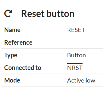
The reset pin is responsible for restarting the microcontroller and placing it into a known state.
A proper reset circuit ensures:
- Reliable startup after power is applied
- Recovery from unexpected faults
- Easy debugging and development
Typical reset circuitry for STM32:
- Pull-up resistor
- Push-button switch
Some MCUs have internal reset circuitry, but MCU manufacturers still recommend external components for improved reliability. Never ignore the reset pin—it often becomes invaluable during development and troubleshooting.
5. Programmer/Debugger
The programmer is the bridge between your computer and the microcontroller.
It is used to:
- Upload firmware
- Debug applications
- Read device information
- Configure device settings
Different microcontrollers use different programming interfaces:
| MCU Family | Common Programmer Interface |
|---|---|
| STM32 | SWD |
| AVR | ISP |
| PIC | ICSP |
| ESP32 | UART |
| ARM Cortex-M | SWD / JTAG |
When designing your hardware, always provide access to the required programming pins. A small programming header can save countless hours during development. For Blue Pill board we have connections available on the board.

Without a proper programming interface, even a perfectly designed circuit can become difficult to use.
So Now coming back to project creation, select PC13 pin -> Left Click & select “GPIO OUTPUT”. THAT’s IT nothing else.
Go to Project Manager Tab at top Right corner & fill the following information.
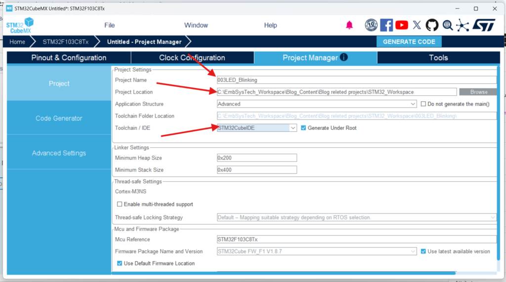
3 things to Check
- Project Name should be correct
- Project Location should be as per your need & as you requested.
- IDE selection should be appropriate. For our tutorial we will be focusing on STM32CubeIDE.
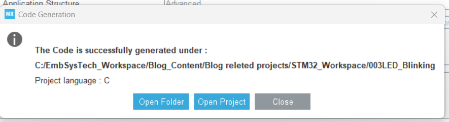
Click On “Generate Code” on top right corner & it will generate the project for you. There might be chances you may get prompted with progress bar but again don’t worry these are just updates which code generator checks If any permissions needed just give it a good look & make sure you are not going anywhere wrong. Finally you will be greeted with following message. Click on “Open Project”
Now as we are not making any big changes in code generator you can close that window once you greeted with STM32CubeIDE window.
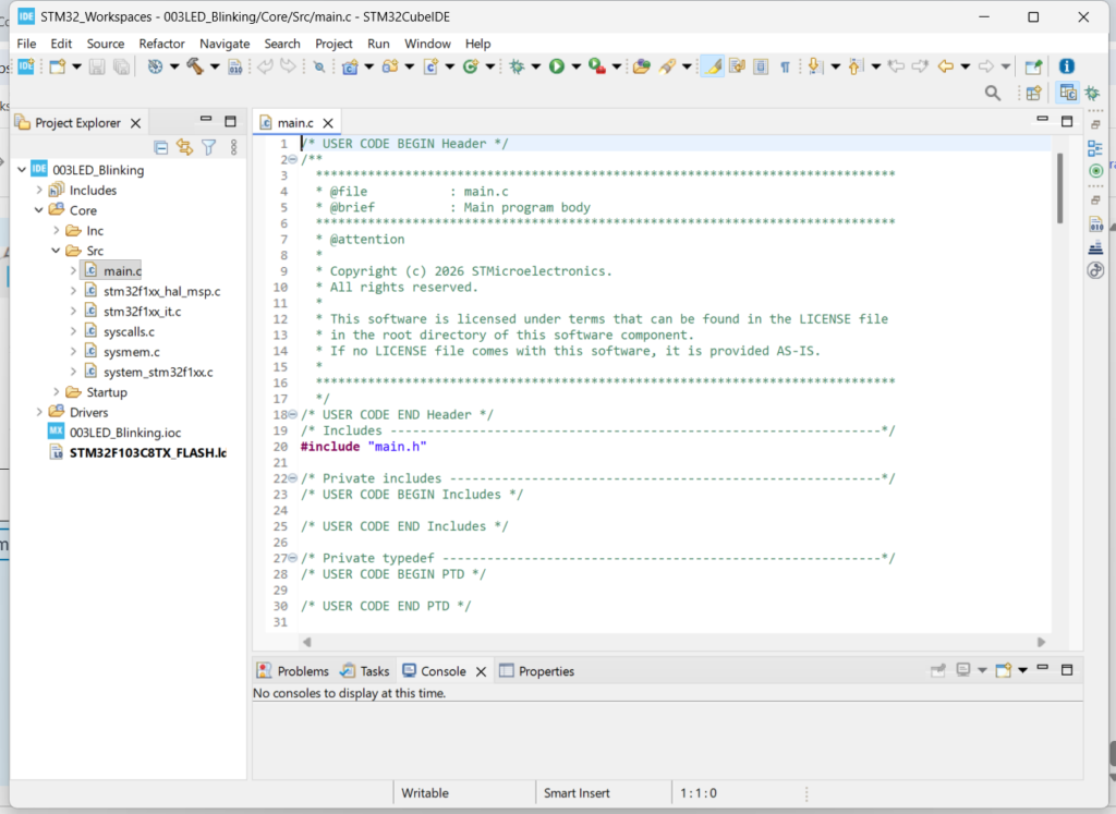
Open your project by click on > and “src” folder you will find “main.c”. As we progress in this course we will explore more about other files & folders for now just scroll down to “while(1)” loop in main.c file. This is known as superloop, where every code repeats till infinity.
Add following lines as
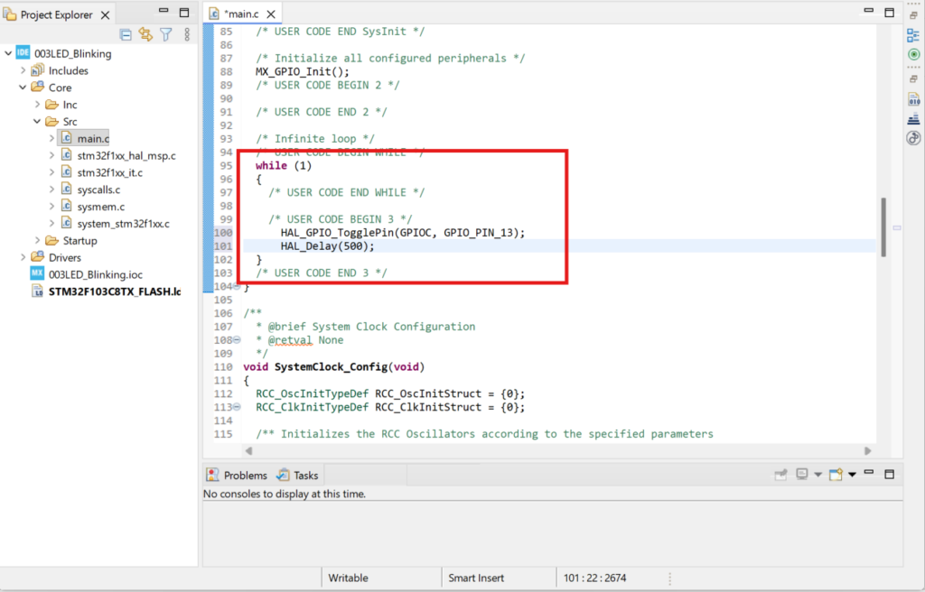
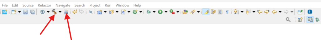
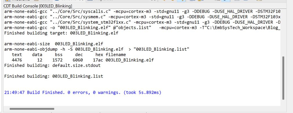
Save the project & build the project form any one of following buttons from ribben bar. Or you can use “Ctrl + B” or Project -> Build All. Any option from your convenience.
You should get following results
Now by clicking on bug like button in top ribbon bar or
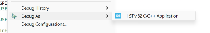
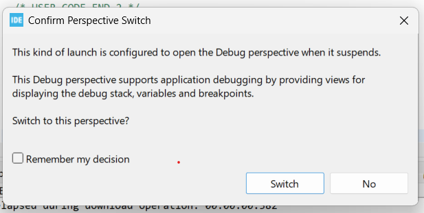
Click on Okay as it gives default debug configurations & start the debug on your board. Give permissions to switch the perspective to Debug window.
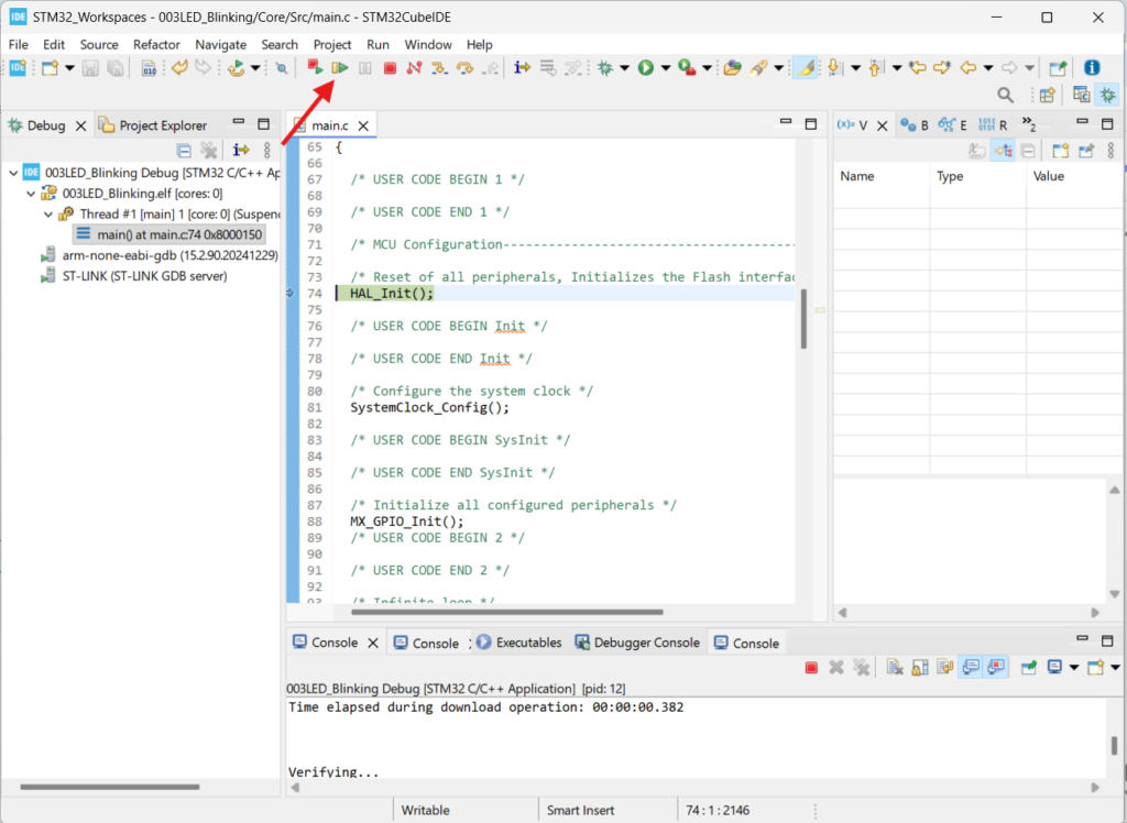
Now by clicking on Play button you can see your board is blinking a LED.
Congratulations on successfully creating your first LED blinking project with the STM32 Blue Pill! This simple project is an important stepping stone toward understanding STM32 microcontrollers, GPIO configuration, and embedded systems development. As you continue your journey, you’ll discover how these fundamental concepts form the foundation for more advanced applications such as sensor interfacing, communication protocols, motor control, and IoT solutions. Stay tuned for my upcoming blogs, where we’ll explore exciting STM32 projects and practical embedded programming techniques step by step. Be sure to follow along and keep experimenting—every project brings you one step closer to becoming a confident embedded systems developer!