Hello Everyone, as you might have guessed by the title, we will create a simple yet effective power supply that can be used for various purposes. However, I recommend not using it with any battery-based equipment or any expensive MCU-based circuitry, as this circuit has direct mains voltage, which may also be very dangerous for handling, so be very careful about it.
In general, every electronic device requires DC power to run, but in our homes, we all receive AC voltage, which is usually very high. To reduce these to manageable limits & convert them to DC(as stated earlier we require low-voltage DC) we either use linear power supplies which come with step-down transformers that drop this voltage to much easier low-level voltages or we use SMPS which again uses transformers with high-frequency components.
Another method uses voltage drop across a passive component to reduce the voltage to the required levels. In this method, we either use a resister or capacitor to drop the voltage to much more manageable levels, which makes the Capacitive type more efficient since its heat dissipation and power loss are very low.
A resistive power supply, on the other hand, dissipates more heat, so the power loss is quite high. A transformer-less power supply is an ideal solution if a circuit requires a very low current of a few milliamperes. Earlier this technique was used in LED bulbs and some old small electronics that run on mains voltage if the current requirement is low. Before designing a transformer with less power supply, some facts about AC dropping through a capacitor or resistor are to be considered.
Considerations:
As we all know when a two resisters are kept in series the input voltage will drop across these two resisters depending upon the series current flows through them. So if even for AC circuits the idea remains same but it added the component i.e. Frequency which may pose lot of calculational difficulties with it. So if we take a simple Ohms Law i.e.
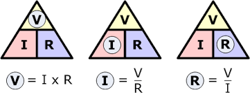
And we use the Ohms law for simple AC calculations, we use RMS values,
I(rms) = V(rms) / Xc
In this, Irms is RMS current value & Vrms is RMS voltage. Before selecting the capacitor, it is necessary to understand how a dropping capacitor behaves when it passes current. The capacitor designed to operate in AC voltage belongs to the ‘X’ category with operating voltage ranging from 250 volts to 600 volts. If the mains frequency is 50 Hz, the reactance (Xc) of the capacitor is:
Xc = 1 / 2 * pi * f * c
where, pi is a mathematical constant with value 3.14,
f is the signal frequency applied to the capacitor,
c is the capacitance value of the given capacitor
As per the given formula, we can determine the resistance of the capacitor which ultimately decides, the current of the circuit ahead. For example, if we take a simple 0.22uF capacitor & use the given formula we get impedance(Xc) around 14475.96 ohm which can deliver roughly 0.01588 Amps ~ 15mAmp which is sufficient to glow a small LED. This implies that before selecting a capacitor you need to define how much current your end circuit needs.
Schematics & PCB Design:
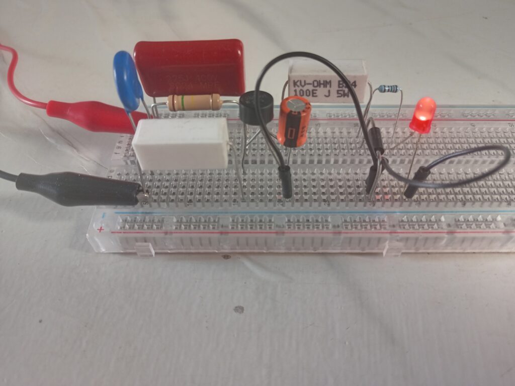
So lets see how to build this circuit. Please go through following circuit diagram.
- Fuse(500mA): Safety First I would recommend a lesser value fuse but unfortunately I got a 500mA fuse. Please use a fast blow fuse as they act much faster in case of an unwanted event.
- MOV(325VAC) : It is basically used to remove any AC voltage transients coming from supply. It acts as a short circuit if supply voltage rise beyond the given MOV range. It will protect the following circuit from any damages. In general it depends on maximum voltage that your circuit can handle. There is a easy trick which you can use. My circuit can handle max 230VAC so MOV range would be 230/0.707 = 325VAC.
- 3.C1(2.2uF/400V): Star of the show the high power capacitor. So let’s first calculate its value by using the formulae we just learned. We have a capacitor with a value of 2.2uF so, try to purchase high-voltage capacitors such as PPC These high-voltage capacitors have ratings from 200V up to Kilovolts. Here I choose 400V capacitors.
- 4.R1(15K/3W): A bleeder resister that removes the stored energy in the capacitor once the main power is removed. The value of this resister needs to be at least 10 times higher than the capacitor impedance otherwise current will flow through the resister and will damage it also the effective resistance of the capacitor should not be varied too much otherwise it will create issues.
- R2(100E/5W): This is a return path resister because when we turn ON the circuit the capacitor will act as a short circuit which will send a big current pulse so to avoid this we are using a power resistor with a lower resistance value to avoid effects during actual run time.
A circuit after a bridge rectifier is self-explanatory. Following are detailed calculations for above circuit.
Calculations:
- Xc = 1 / (2 x 3.14 x 50 x 2.2uF) = 1446.86 ohm
- X1 = Xc1//R1 = (Xc1 x R1)/(Xc1 + R1) = 1446.86 // 15000 = 1319.57
- Mains Voltage = 230VAC
- Zener Voltage = 5.1 VDC
- Diode Drop = 2 x 0.7V = 1.4V
- I = (Vin – Vd – Vz)/(X1 + R2) = (230 – 1.4 – 5.1)/ (1319.57 + 100) = 0.15744A ~ 158mA
- As VX1 = X1 x I = 1319.57 x 0.15744 = 207.75 VAC
- PR1 = (V x V) / R1 = (207.75 x 207.75)/ 15000 = 2.87 W ~ 3 W
- PR2 = I x I x R2 = 0.15744 x 0.15744 x 100 = 2.47 W ~ 3 W
- R1 = 15K / 3W *
- R2 = 100E / 3W *
- Zener Diode Pz = Vz x Imax = 5.1V x 0.15744 = 0.802W ~ 1W
- D2 = 5.1V / 1W *
- Diode Bridge 1 Amp will be good
- Zener Resister voltage Vzr= (Vin – VX1 – Vz – Vd) = 230 – 207.75 – 5.1 – 1.4 = 15.5V
- Zener Resister = Vzr / Imax = 15.5 / 0.15744 = 98.4 ohm ~ 100 ohm (Here choose higher value resistance not lower for safety)
- Zener Resister Wattage Pzr = (Vzr x Vzr) / Rzr = (15.5 x 15.5) / 100 = 2.40 W ~ 3 W
- Zener Resister = 100 ohm / 3 W *
- * For a given wattage value you can purchase the exact wattage or higher wattage component to avoid any mishaps.
Working:
So according to the given calculations I created the circuit.
Usage :
The given circuit can be used as a simple power supply in many ways as I mentioned lots of cheap products still use this technique as their main power supply. In cheap LED bulbs, some of the battery power stuff uses this circuit to charge the main battery. Also, be careful with power ratings as the given power ratings are according to mathematical/theoretical calculations so in practical circuits, the values may vary which can eventually lead to damages be very careful while using something else or purchasing things.
Tips:
- Do not use this circuit for any high power stuff as for more voltage or current the capacitor value may become unstable and values of the actual components will not be practical.
- Do not use this circuit for battery stuff especially for battery charging as this circuit does have good protections and it may lead to accident as you are playing with direct mains voltage.
Cautions : Don’t try this circuit if you don’t have much experience with electronics. Care should be taken while testing or using this circuit. Don’t touch at any points of the circuit since some points of this circuit is at Mains Potential. After constructing and testing, enclose the circuit in a plastic casing without touching PCB and plastic case. The board should be properly earthed to avoid shock hazards.